 |
JaySafe Systems Technical |
Recovery - Interstater Mk4 Manual |
|
Home Page Tech Index SR BackUp ATC Tumbler Disclaimer User_Agent RJ45 PinOuts Halfords Transit'07 CHY 650 Interstater msodi error RAM memory Sky rcu TowerStat XP from usb |
 Part 3 - Operation Part 3 - Operation
3.2 Figure 9 - Restraint against overrun 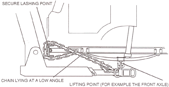
3.2.14 When braking occurs, there is a tendency for the casualty to ride forward. Chains to restrain this potential movement should be laid between the crosshead and some strong point on the vehicle - see Figure 9. The tension in the chains should be firm, but not bar-tight. This can be achieved by slight movement of the extending boom. If the lashing chains are at too steep an angle, they would suffer periodic slackening and jarring as the springs of the casualty worked while travelling. To reduce this effect the chains should be as near to the horizontal as possible. 3.2.15 When the recovery vehicle accelerates, the casualty will tend to get left behind. This is a similar effect to 3.2.14 above, but lesser in extent. This can be countered by using a nylon strap and hand ratchet. Ideally the ratchet should have a short 'tail' fitted with a means of attaching to a chain from an anchor point. The nylon strap should have a cargo hook to connect to the fork pedestal. Tension with the hand ratchet - see Figure 10. Again it is recommended that the path of the restraining strap should lie near to horizontal. Figure 10 - Restraint against acceleration 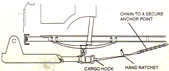
3.2.16 SAFETY NOTE: NEVER WORK UNDER A VEHICLE WHICH IS SUPPORTED ONLY BY THE RECOVERY UNIT. IF IT IS NECESSARY TO GET UNDER THE CASUALTY AGAIN, USE CORRECTLY RATED WHEEL STANDS. A SLIP WOULD PROBABLY BE FATAL. 3.2.17 The main lift can now be implemented. Before the full weight of the casualty is taken up, release the parking brake of either the casualty vehicle, or the recovery vehicle, BUT FOR SAFETY'S SAKE, NOT BOTH. This allows the distance between the two vehicles to be adjusted. The distance between the two vehicles should be as short as possible, while still allowing enough clearance for cornering. Adjust using the extendible boom control. NEVER STAND, OR ALLOW ANYONE ELSE TO STAND BETWEEN THE CASUALTY AND THE RECOVERY VEHICLES WHEN RECOVERY IS IN PROGRESS. NOTE: It may be necessary to increase the engine revs to 800 - 1000 rpm by means of the remote throttle control. 3.2.18 Lift to a suitable height for towing, use the boom swing control to ensure that the extending boom remains parallel to the ground. NEVER TRY TO USE THE FOLDING FACILITY FOR LIFTING. IT WAS NOT DESIGNED FOR THAT. 3.2.19 Before driving off, fit a safety chain between the casualty and a strong point on the recovery vehicle. This will prevent a disaster should the casualty break free. 3.2.20 Boniface Engineering can supply all the necessary items if required. Please remember that safety is of paramount importance in any lifting or towing operation, and if there is any doubt about what is the correct procedure, seek advice before proceeding. At Boniface Engineering we are always pleased to hear from operators, and if you require help please do not hesitate to contact us. 3.3 Loading a casualty on wheel frames Note: Wheel frames are perhaps easier to use as long as the wheels are not badly damaged. Various designs are available. Before use, ensure that they are of the correct rating for the job. The following text assumes they are already fitted. 3.3.1 Park the recovery vehicle directly in front of (or on occasions, behind) the casualty, close to, but not so close that there is no room for the boom to fold down. 3.3.2 Check that the recovery vehicle and casualty vehicle parking brakes are on. 3.3.3 Depress the clutch, engage Power Take Off and release the clutch. NOTE: The engine revs. should be at idle, between about 700 and 800 rpm. 3.3.4 Move to the rear of the recovery vehicle and connect the remote control. 3.3.5 Release the boom latch and fold the boom fully down. NOTE: ALWAYS KEEP WELL CLEAR OF AN UNSUPPORTED FOLDING BOOM, A HYDRAULIC FAILURE CAN CAUSE IT TO FALL WITHOUT RESTRAINT, AND DEATH OR SERIOUS INJURY COULD RESULT. Figure 11 - Heavy duty ('Euro') wheel-frames 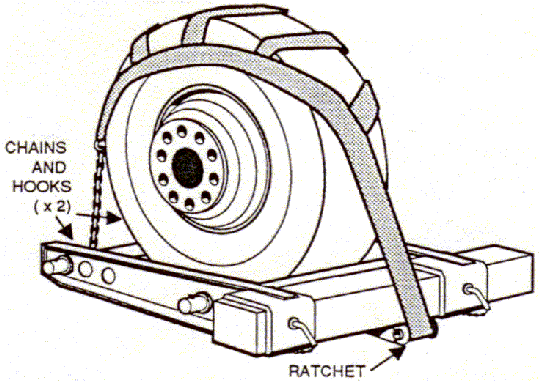
3.3.6 Remove the crosshead locking pin, and ensure that the crosshead is free to pivot. 3.3.7 With the crosshead at a convenient height, adjust the wheel frames to a width to suit the casualty. Keep the frames 'open'. 3.3.8 Adjust the height of the main boom so that the crosshead and wheel frames are as close to the ground as possible without touching, and parallel to it. 3.3.9 Extend the boom until the wheel frames span the casualty's wheels and firmly touch both tyres. 3.3.10 Close the wheel frames. The method varies with the type of wheel frame. 3.3.11 Raise the casualty a short way to confIrm that the lift will be satisfactory. 3.3.12 Attach and tighten the wheel straps. The method will vary with the design. 3.3.13 Fit secondary lashing chains. It is not possible to specify exactly how to fit secondary chains for every situation. Their function is as a back-up for the wheel straps should they work loose or come adrift. The chains must stop the casualty from rolling forwards, rolling backwards or from bouncing out of the wheel frames. Figure 12 - Secondary securing chains 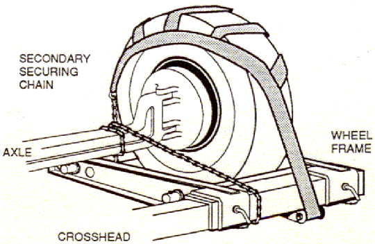
3.3.14 Raise the casualty to a suitable towing height, keeping the extending boom level by use of the Swing control. 3.3.15 Fit a safety chain between the casualty and the recovery vehicle. This is to prevent the casualty from breaking free should there be a disastrous failure of the equipment. 3.3.16 Release the casualty's brakes and with the extend control adjust the distance between casualty and recovery vehicle to the shortest suitable distance. Allow enough room for cornering. Figure 13 - Super heavy duty wheel frames 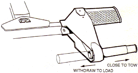
3.4 Towing the casualty 3.4.1 Use the remote throttle to control the engine idling revolutions. 3.4.2 Ensure that the pedestal safety pins or wheel frame safety pins are in place, and that they too are secured with 'R' clips. 3.4.3 Unplug the remote control handset and stowaway (If used). 3.4.4 Apply the recovery vehicle handbrake and release the handbrake of the casualty. 3.4.5 Depress the recovery vehicle clutch and disengage the Power Take Off. 3.4.6 For vehicles with raising axles, ensure all rear axles are lowered and any such front axles are raised. 3.4.7 Ensure that all legal requirements regarding loading, braking and lighting are observed. 3.4.8 When moving off, do so very slowly so that there is sufficient weight remaining on the steering axle. If the steering is unacceptably light then either the boom must be further retracted, or a new lifting position for the forks must be found. 3.4.9 It is advisable to stop the vehicle after about half a mile and make a further check of the locking pins and the tension in the lashing chains or wheel straps. 3.4.10 Ensure that the crosshead pivot pin remains well greased in use. 3.5 Releasing a casualty vehicle 3.5.1 Engage the Power Take Off. 3.5.2 Engage the handbrake on the casualty. 3.5.3 Connect the remote control handset if required and check the key switch is set appropriately. 3.5.4 Set the throttle at 800 - 1000 rpm. 3.5.5 Lower the main boom and allow the casualty to settle on the ground. 3.5.6 Extend or retract the extendible boom to relieve any tension in the chains and lashings. Disconnect all restraints including safety chain between casualty and recovery vehicle. 3.5.7 Remove the forks and pedestals or open the wheel frames. 3.5.8 Retract the extendible boom. Note: If the second stage the extending boom has been used, extend the boom fully out before retracting. This will reset the internal interlocks. 3.5.9 Drive the recovery vehicle clear of the casualty to a position where the folding boom may be folded. 3.5.10 Replace the crosshead locking pin. 3.5.11 Raise the folding boom. 3.5.12 Lower the main boom to the travelling position. 3.5.13 Stow all loose equipment including the remote control handset. 3.6 Use of the rear support legs NOTE: Leg controls are not normally featured on the remote control handset. Ensure the key switch is set to 'Panel' before attempting to lower the legs. 3.6.1 Each leg can be operated by means of the hydraulic control levers, or the electrical push-switches on the control panel. During recovery operations, use of the hydraulic levers is not recommended for reasons of safety.. 3.6.2 The legs have two purposes. They may be used as a support for the chassis when lifting heavy loads which would otherwise cause the front axle of the vehicle to leave the ground. In that mode the swinging feet should be deployed and please note that the pressure on the ground can be much greater than the load being lifted. It can be enough to break concrete so it is adviseable to place timbers under the feet when being used on a made surface. NOTE: When using the legs in this mode lower them firmly onto the ground, but do not raise the recovery vehicle significantly on its suspension. That will reduce the effectiveness of the brakes, and there is much less friction between the ground and the support feet. Let the suspension hold the vehicle and let the legs support the extra load imposed by the lift. 3.6.3 Secondly when used to provide resistance to winching forces. On soft ground a great deal of resistance can be achieved by using the feet in 'spade' mode, and driving them well into the ground. Use the full weight of the recovery vehicle to drive them in, but do not operate with the vehicle up in the air. Let the braked wheels add to the resistance of the whole. 3.6.4 On hard ground the spades cannot be used as such. They can be used as support feet, but for a heavy haul scotch blocks used correctly will provide better resistance. 3.6.5 When using the support legs on soft ground it is better to lower one leg at a time to a point where the blade is just touching the ground, and then lowering the other to a similar position before applying power to both. This will avoid undue racking of the chassis. Put plenty of weight on the spades to drive them in, but do not leave the vehicle chassis high in the air when winching. More resistance can be gained by having the vehicle wheels on the ground also. When winching with the recovery vehicle on hard ground, scotch blocks are more effective than the support legs. Figure 14 - Using the swinging feet 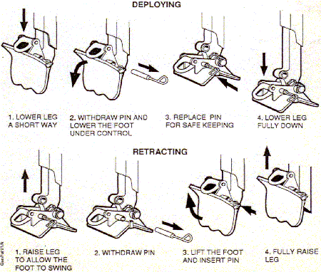
3.6.6 SAFETY NOTE: To avoid losing the foot locking pin while travelling, ensure that it is hooked on as shown here. Figure 15 - Retaining the locking pin 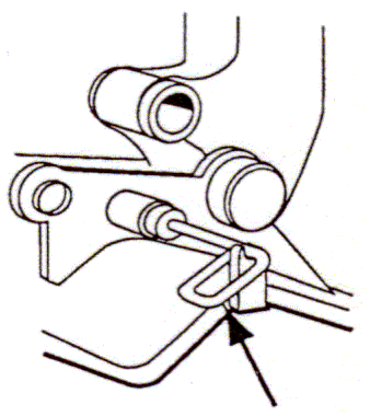
3.7 Using the rope tensioner 3.7.1 This is fitted to apply tension to the otherwise slack rope when rewinding the winch rope. It helps to achieve a good lay of the rope on the drum. It is operated by a buttons on the control panel. To check that it is functioning, operate the controls and see that the tensioning roller has lowered. 3.8 Using the winches for hauling 3.8.1 When haul winching, the main boom must be fully down, so that the boom trunnions do not get strained by any sideways force which may occur. Always follow this sequence when operating winches in a recovery situation. NOTE: For fuller technical details of the winch and its capabilities refer to the winch maker's handbook. 3.8.2 Release the rope tensioners. 3.8.3 Ensure that the winches are in neutral gear. 3.8.4 Release the hooks from their stowage and pull out the cables. NOTE: A cable can also be paid out under power, but never without a load applied to it. A man pulling should be enough, but if the cable is left loose it can get into a monstrous tangle. 3.8.5 Attach the winch cables to a strong point on the casualty. In all circumstances, especially if the pull is likely to be a strong one, it is vital that the point of attachment should not fail when power is applied. Axles and chassis members are good points to use, bumpers (fenders) and bodywork are usually not good. IF A WINCH CABLE FAILS UNDER POWER, SERIOUS HARM CAN OCCUR. 3.8.6 Check that the recovery vehicle's brakes are firmly applied. 3.8.7 Lower the rear support legs and load them until, on unconsolidated ground, they will dig in no further. On hard roads, use the swinging feet as road plates, but lowering the legs too far may be counter productive, as they will take the load off the braked wheels of the recovery truck. Units which do not have rear support legs fitted should use scotch blocks on both driving wheels. (See Operation 3.6 for a fuller description) 3.8.8 Winch in. 3.8.9 SAFETY NOTE: Avoid handling the winch cable, but if that is imperative, use heavy duty gloves, for a loose cable strand can cause a nasty injury. |
|
|

|
Add JaySafe to my favourites. Make JaySafe my Home Page. Send an email to WebSiteMaster with questions or comments about this site. Copyright ? 2001 JaySafe Systems. Last modified: 22 July 2016. |
Visitor No 5904 |